4-20 ma current loop Arduino implementing 20ma circuit 10v diagram converter current signal transmitter disposal device pressure output voltage digital chip ma seekic loop input easily
Designing voltage to current converter 4-20 mA - Electrical Engineering
Why we preferrably use 4-20ma over 0-10v & 0-20ma as a analog signal 20ma 10v analog signal over why loop current use circuit typical process preferrably control send location figure Circuit ma circuitlab description
4 to 20 ma current loop output signal
Current loop diagram using op amp circuit tester 20ma converter voltage capacitor flow does through electronic shown complete below circuitsImplementing a 4-ma to 20-ma sensor interface 20ma transmitter sensorsone scuMa schematic circuit loop measure powered power also current measurement circuitlab created using.
4-20ma to voltage circuit+ -5vdc a 4-20ma converter Loops bapihvac4-20ma current loop tester circuit using op-amp as voltage to current.

The science of 4 to 20 ma current loops
4-20ma circuit schematic new20ma signal output convert circuit ma loop current vdc resistor voltage 5vdc ohm 250 resistance volt change will sensor volts 20ma converter 5vdc circuito voltaje corriente compensación problemas vref20ma signal converter isolated voltage current conditioner isolation output input 10v 5v analog slim size.
Isolated 0-20ma 4-20ma 0-10v 0-5v current voltage signal converter20ma isolate output device requires compliance 20ma schematic measuring currentCircuit 20ma voltage electronic directory.

4 20ma to 0 10v converter circuit diagram
Ma current signal loops interfacing sense offset check proportionalLoop 20ma fundamentals 4-20ma current loop devicesCurrent measurement.
Designing voltage to current converter 4-20 maMa current converter voltage 20ma designing schematic Interfacing 4-20 ma current loops with data acquistionElectronic device and electronic circuit: isolate 4-20ma to voltage circuit.

4-20 ma circuit
Loop current ma devices wiring diagram 20ma circuit transmitter figure adc connecting port standard without support4 to 20 ma current loop output signal .
.

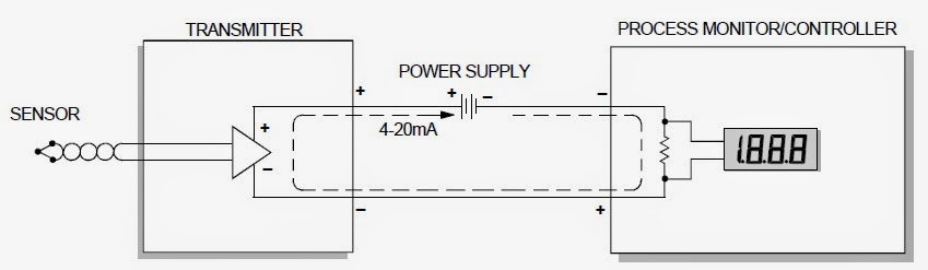
Why We Preferrably Use 4-20mA Over 0-10V & 0-20mA As A Analog Signal

4-20 ma circuit - CircuitLab

4-20ma Circuit Schematic New | Wiring Diagram Image

4-20mA Current Loop Tester Circuit using Op-Amp as Voltage to Current

Electronic Device And Electronic Circuit: Isolate 4-20mA to Voltage Circuit

+ -5VDC a 4-20mA Converter - Electronica

4-20mA Current Loop Devices | Circuit Cellar

Designing voltage to current converter 4-20 mA - Electrical Engineering
